So! I'd been working on a 3d-Printed version of Captain Slug's
Durendal for quite a while, had posted parts of it places, then my printer died, then I brought it back to life and now it
appears ready for publishing.
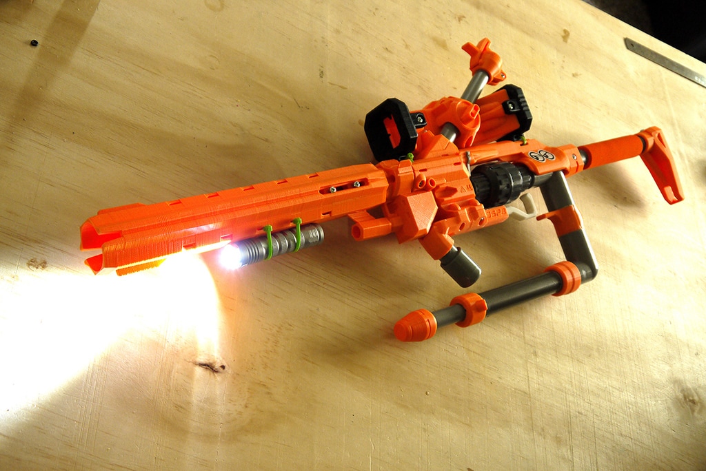
Without further delay, I am pleased to present:
3d Printed Durendal ![image_23.JPG]() Disclaimer: I am not responsible for your poor use of tools, work safely, wear eyeglasses, don't aim at people or pets, read all instructions prior to assembly, etc. etc. You're on your own, mind yourself.First, you'll need to print these things:
Disclaimer: I am not responsible for your poor use of tools, work safely, wear eyeglasses, don't aim at people or pets, read all instructions prior to assembly, etc. etc. You're on your own, mind yourself.First, you'll need to print these things:One of each of these files, I use 2mm walls an 100% fill for these since it's like a 2g/10minute difference. I've tried them with 20%, they can work, but for the cost it's worth the trade to avoid breakage:
Catch:
![Attached File]() Catch FIttingv4ex.stl 3.07MB
15 downloads
Catch FIttingv4ex.stl 3.07MB
15 downloadsDrill Guide:
![Attached File]() Drill Guide.stl 628.21KB
9 downloads
Drill Guide.stl 628.21KB
9 downloadsPlunger Head:
![Attached File]() MK10_PH.stl 1.08MB
13 downloads
MK10_PH.stl 1.08MB
13 downloadsYou'll need
either the D-grip and trigger
or the Caliburn grip and trigger parts. Both should take about the same time; I think I printed the D-grip at 3mm walls just to be sure it was going to survive (an earlier version sheared off on me before I thickened the area), otherwise 2mm and 20%.
D-Grip:![Attached File]() DGrip V3.stl 9.61MB
9 downloads
DGrip V3.stl 9.61MB
9 downloads![Attached File]() DGrip Trigger V3.stl 927.72KB
11 downloads Caliburn Grip
DGrip Trigger V3.stl 927.72KB
11 downloads Caliburn Grip (Note - I've printed this for a Caliburn, but not for this project. I expect it'll work, but it's untested. You'll also need all the pins and parts for a caliburn handle, not listed in the partslist):
![Attached File]() Caliburn Grip A.stl 1.03MB
8 downloads
Caliburn Grip A.stl 1.03MB
8 downloads![Attached File]() Caliburn Grip B.stl 1.03MB
8 downloads
Caliburn Grip B.stl 1.03MB
8 downloads![Attached File]() Caliburn Grip C.stl 575.96KB
8 downloads
Caliburn Grip C.stl 575.96KB
8 downloads![Attached File]() Caliburn Trigger.stl 767.17KB
7 downloads
Caliburn Trigger.stl 767.17KB
7 downloads If your printer uses layers instead of dimensions, divide the desired wall dimension by your nozzle size to get the total layers; for most with a 0.4mm nozzle you should be talking 5-8 layers.
Then, you'll need: Tools:Drill + Bits (at a minimum, 1/8" & 1/4")
Screw drivers for your screw heads
A saw (coping saws are cheap and work; any regular wood saw is probably possible)
Pencil or marking tool
Electrical or packing tape
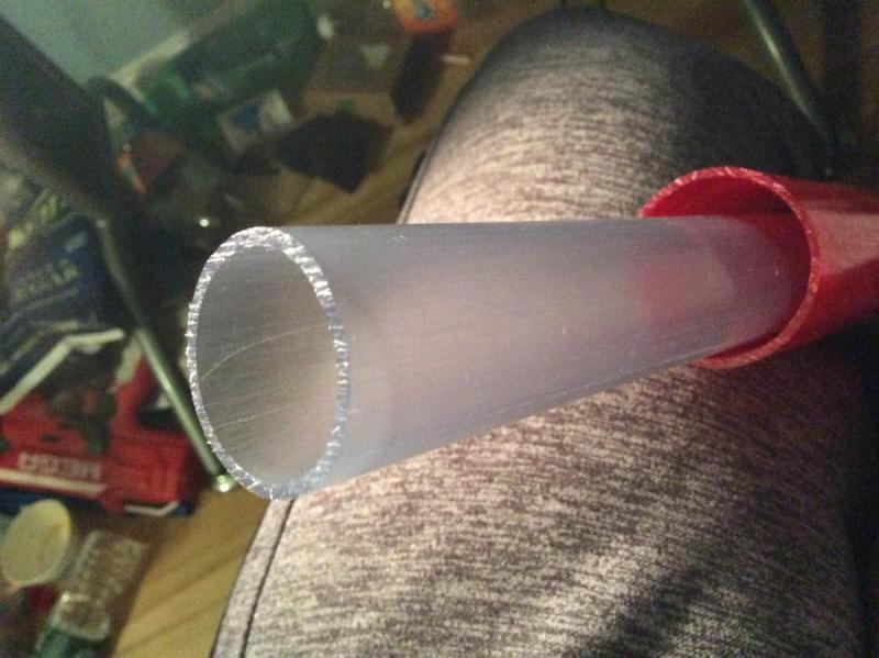
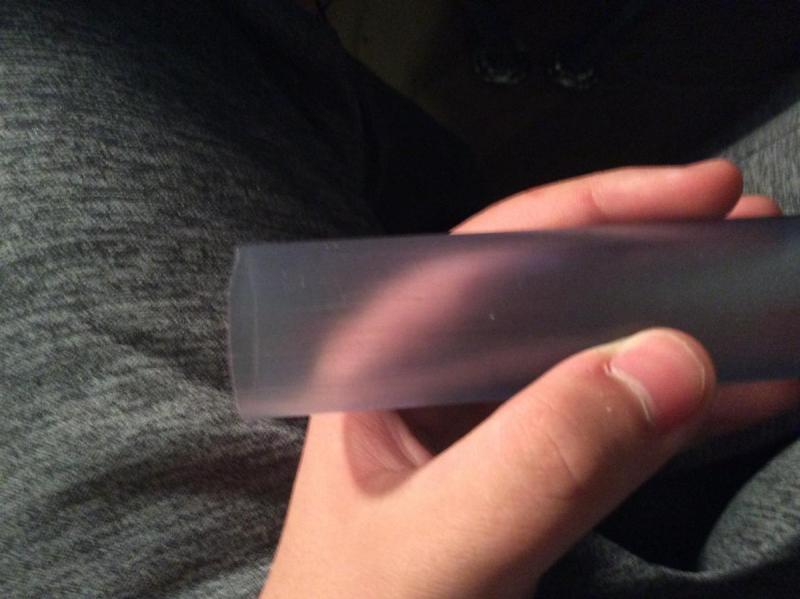
Materials:![image_123923953.JPG]()
13" of 1-1/4" Sch.40 PVC
~15" of 1/2" Dowel (Plastic or Wood, shouldn't matter though I'd use wood stronger than birch),
optionally cut after installing(1) 1-1/4" Fender Washer
(2) #8x1.5" machine screws and nuts
(1) #8x3/4" machine screw
(1) #8 washer (to keep the catch spring from entering the hole in the PT)
(1) #6X3/4" machine screw (could be #8 if you bore it out)
(1) Catch spring. I think I'm using a cut-down ACE#2, but they were all mixed up in the drawer.
(2) 3/8"x~3/4" Barrel nuts (length isn't important other than for looks) & Screws (usually 1/4" dia, IIRC 1" long, smaller dia will work and there's some room for greater length if needed)
(1) 1"+ long Wood screw for attaching fender washer to dowel (and washer if needed). Size isn't critical, I used a simpson pan-head screw I had lying around.
(2+) 1/2" long Screws to attach front bushing. Again, type, size, etc. aren't important - some people like socket heads, some like pan-head phillips, some like hex heads. Use what you want/have available locally.
(1) Dash 216 oring. Nominally 1-1/8" ID, 1-3/8" OD, 1/8" x-section; sometimes listed nominally instead of by dash number and kept in plumbing section.
(1) 1"x1/2" Sch.40 PVC Bushing
(1) Mainspring ([
[k25]]/6, AR15 buffer, etc)
Something to use as a pull-handle for your plunger (1/2" CPVC T-fitting, Key ring, whatever)
Oatey's silicone plumber's grease.
This guide is for my non-omni-plunger rod, if you want an omni-plunger rod use materials and methods for one of those. The one I tried to make out of a wood dowel broke.
Once you've gotten all that together: ![image_.JPG]()
Slip your printed
Drill Guide over the end of your cut 1-1/4" PVC. Note that one of the 5 holes is offset and unpaired, this is your catch hole, this should be towards the back of the blaster. You can determine the exact position by lining up the bushing, mainspring, and drill guide such that they all just touch and the lip of the bushing is on the front of the PVC. Ensure your grip has space on either end for the barrel nuts & screws. Once your guide is in place, either mark the positions of the holes and remove the guide (To keep it from being damaged and use again) or drill them out in place (if this is a one-off or you'll print more).
(This guide uses the D-Handle, the caliburn one should be similar but will require assembly as per the
caliburn instructions).
![image_12.JPG]()
Assemble your handle. For the D-handle, this is setting a #6 screw through the hole shown into the trigger. For the caliburn, it'll be per the caliburn instructions.
![image_1.JPG]()
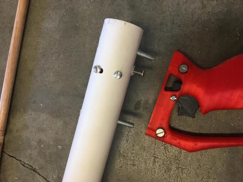
Use the notches on the side of your grip to mark where you'll need to drill for your barrel nuts. These holes should align along the length of the tube with the catch hole from the drill guide, if you can make a mark lengthwise that will help but shouldn't be nessecary. Position the trigger in the D-handle or the Caliburn handle such that it rests over the catch hole, then mark and drill these holes to fit your barrel-bolts.
Drill all the way through the 1-1/4" PVC and make holes large enough to install your barrel-bolts, in my case I used 1/4" or something. Also chamfer the holes with your larger bit (or a proper counter sink) so your bolts sit lower in the PT.
![image_123.JPG]()
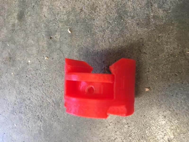
Gather your catch pieces and arrange them like so.
![image_1239.JPG]()
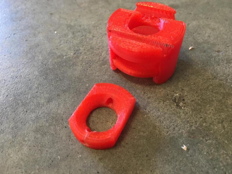
Stack them up as arranged
![image_648.JPG]()
Note which direction the center piece (the catch) goes - the smaller end should point toward the catch hole drilled in your PVC, and the chamfered side should be facing toward the front of the blaster (toward the largest piece in the catch assembly). The catch should slide freely.
![image_12392.JPG]()
This is the orientation that the catch assembly goes in. Make sure to have it right-way down so the catch can slide down freely!
![image_123923.JPG]()
Begin installing the #8 1-1/2" bolts, start with the narrower hole in the catch assembly and move to the wider. If necessary, make one of the sets of holes through the 1-1/4" PVC 'sloppy' so the bolts will allign. If really nessecary, do both; these bolts are to keep the
spring in place not the catch; that'll stay when you put the catch spring in.
Which you should also do now.
![image_1239239.JPG]()
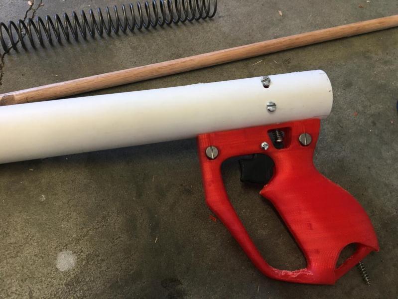
Insert your barrel nuts and bolts and tighten down.
![image_12392395.JPG]()
![image_211.JPG]()
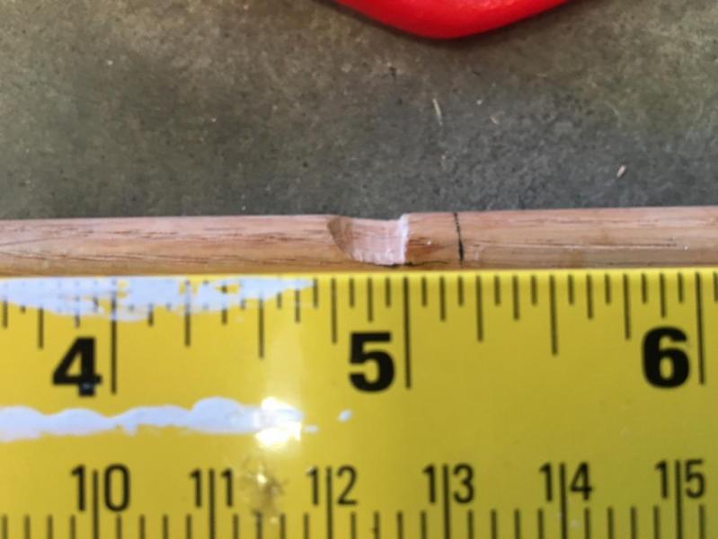
Cut a notch like this 5" back from the front of the plunger rod dowel. Flat at 5", sloped down to it; ideally with the flat spot. If you want to make an omni-catch you could do that too. If you know you need a different amount of compression this may be adjusted to suit.
![image_2.JPG]()
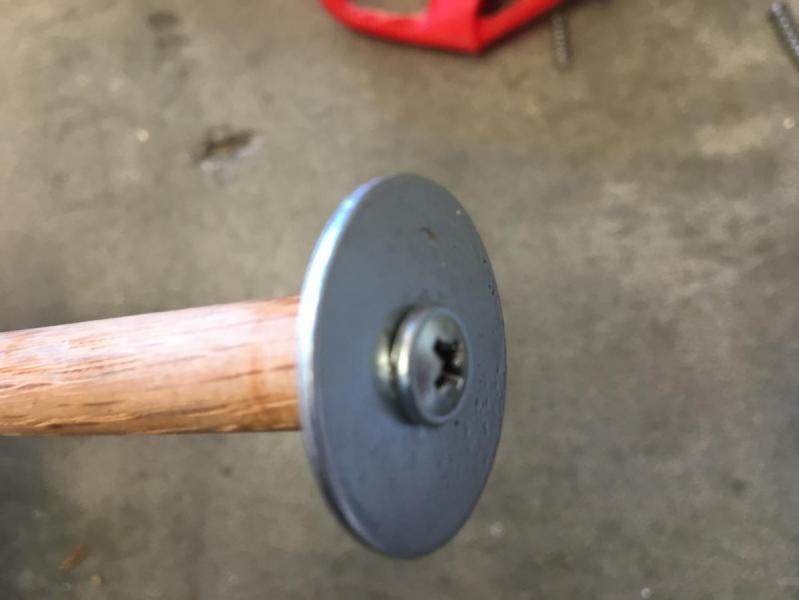
Drill a
centered 1/8" hole into the front of your plunger rod dowel, screw in the wood screw and fender washer (and smaller washer if needed).
![image_21.JPG]()
Put the -216 Oring on the plunger head piece, slide both onto the dowel so they sit like this against the fender washer. The fender washer will put this piece in compression only, the printed part just acts to hold the oring in place.
![image_22.JPG]()
Add the spring, thread the plunger rod through the front of the blaster and the catch piece. Using an actual dowel uncut is nice at this point, because you have extra length to use to guide it into place. Lube up your oring with the Oatey's. Cut your dowel to length and add your handle once they're installed; either in place or mark them and cut them out of the blaster.
![image_23.JPG]()
And we've come full-circle. Put the bushing in - use tape to pad it out as needed so air doesn't leak around it - and thread screws of your choice into it to keep it popping back out. Add a barrel or adapter and you're good to go!