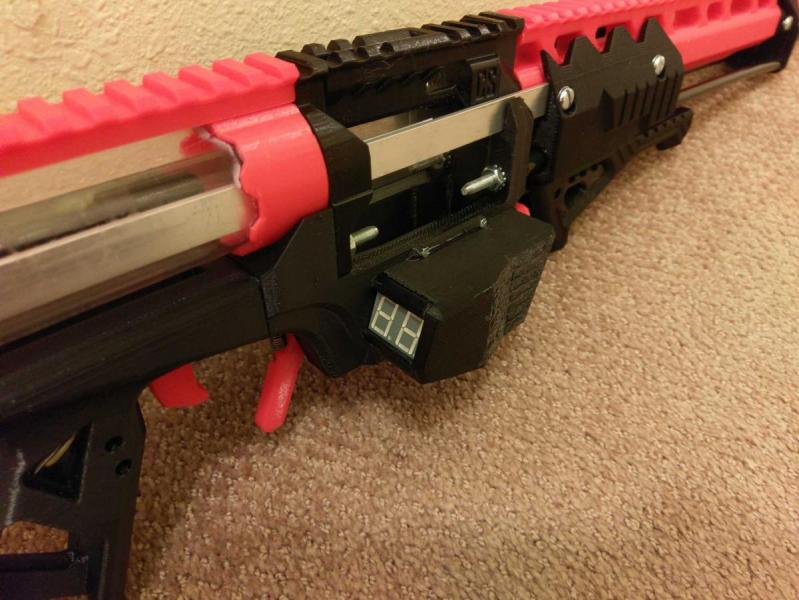
Here I present my Caliburn modified with an integrated ammo counter. Fittingly, I'm calling it the Countiburn.

Video showing operation:
Note that this version is left handed. Right handed files will be up this weekend.
Credit/Inspiration
Caliburn (duh)
Ammo counter script (this guy's mag toggle method directly inspired mine)
Another ammo counter script (borrowed his number display method)
Bill of Materials
Adafruit Trinket Pro 3V
Lipo Backpack for Trinket
Adafruit 1200 mAh Lipo
Assorted Jumpers
Slide Switch
Ligitek 2-digit Seven Segment Display Common Anode
M2x10 mm bolts (DO NOT GET FLAT HEADS LIKE ME IF YOU DON’T HATE YOURSELF)
Tools Needed
Variable wattage soldering iron
3D printer
Helping hands for soldering
Electrical solder (thin, .032", I like lead-based but use whatever you're comfortable with)
Heat shrink tubing
Solder sucker
Multimeter
Datasheets/Useful Links
Ligitek display pinouts
Windows driver for Trinket Pro
Setting up Arduino IDE
How to install and use libraries (my code uses one)
Soldering to PCB guide
Code/Libraries
 Countiburn Code.zip 7.07KB
0 downloads
Countiburn Code.zip 7.07KB
0 downloads
Thingiverse Link
Countiburn
Okay, first of all get your trinket pro set up. Follow the linked guides. I can answer questions if people are struggling. You can also google your problem/error code and get answers that way.
At this point you also want to start printing everything from the thingiverse link. As explained in the link, there are two sets of most components: with built-in support and without. If you have a multi material printer/dedicated support material use the without version. If you’re doing single material PLA I suggest using the versions that include support. It is drawn in by hand rather than auto-generated and is optimized for a .4mm nozzle.
Next let’s assemble our trinket. Unpack the trinket and the lipo backpack.
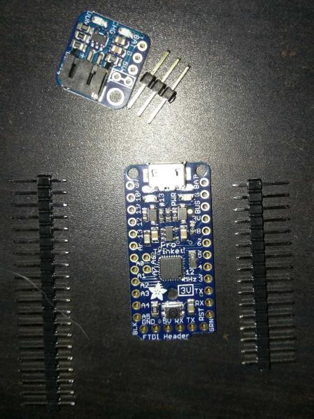
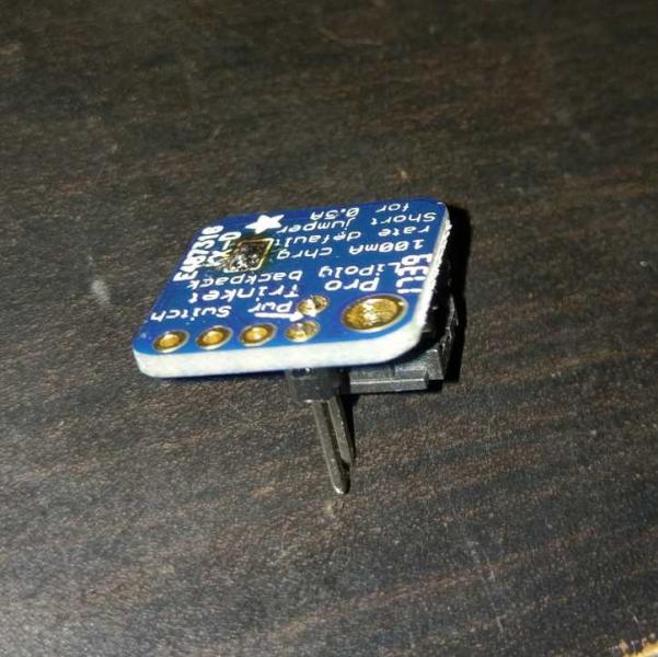
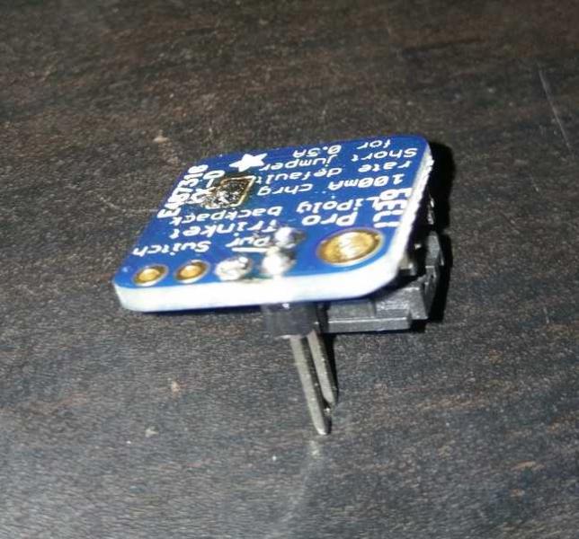
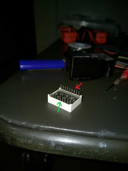
Snip your headers and arrange your pins as shown.
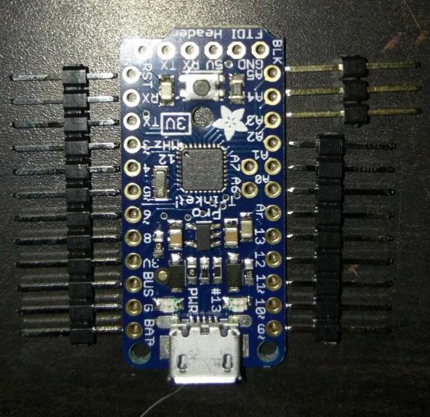
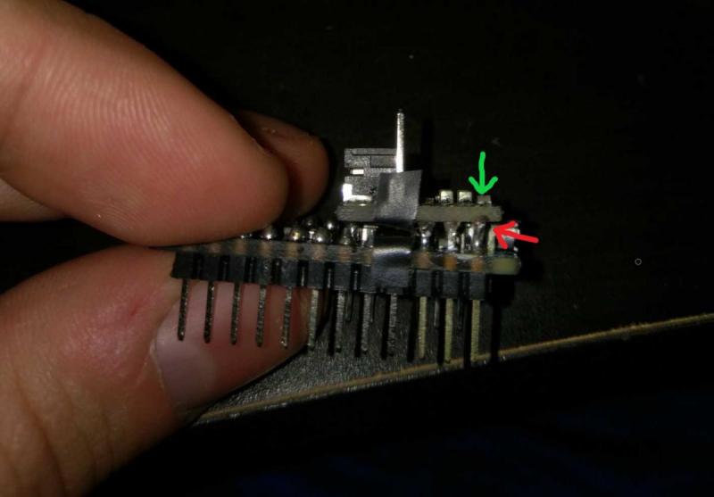
Solder your pins on. See the linked guide for help, the videos included are the most useful parts.
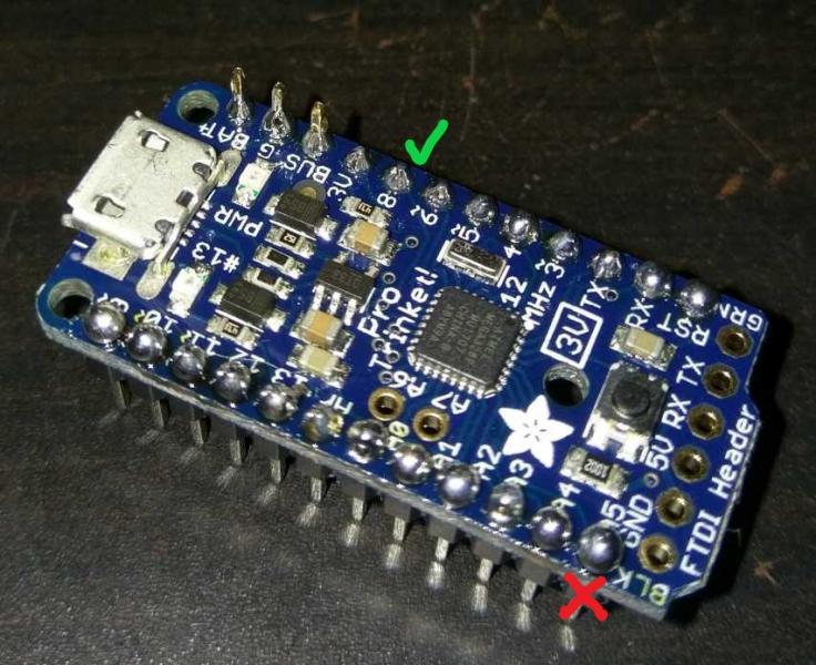
Notice the bulbous joint at the red x, and the hershey’s kiss shaped joint at the green check. Try to get them looking like the latter. You can tell which side I started on.
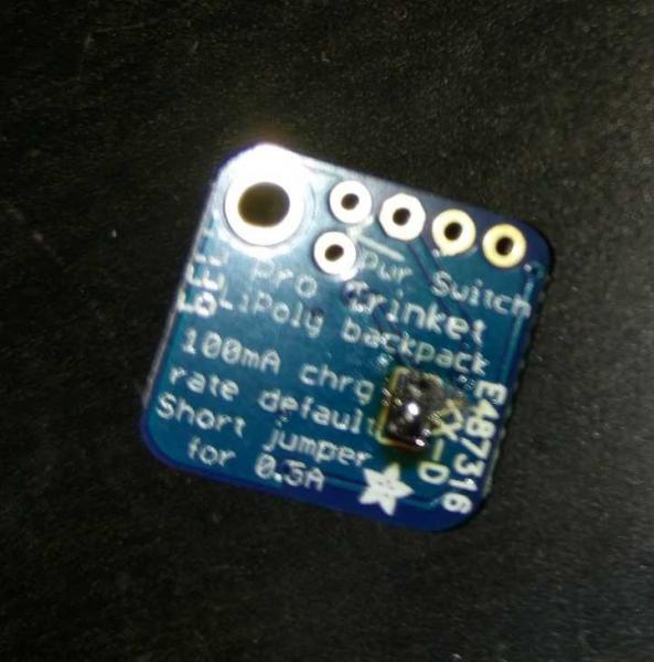
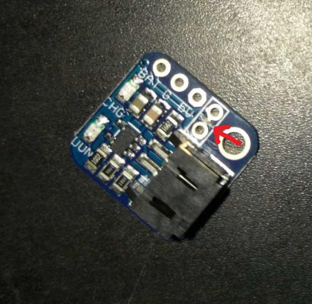
Next grab your backpack, flip it over, and note the bit circled in red.

We need to solder closed that bridge so charging the lipo doesn’t take forever. Only do this if you use the lipo included in the BOM. Adafruit suggested minimum capacity of 500 mAh to close this bridge and enable higher current charging.
Next flip the backpack right side up and use a sharp blade to break the contact pointed to by the arrow. I have already cut this contact in the below image. Use a multimeter to make sure it’s broken.
Use leftover pin headers to solder pins to the pinouts between the cut bridge.
Apply e-tape as shown. We don’t want any pins shorted when we solder on the backpack.
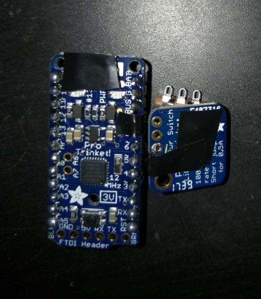
Solder on the backpack. Note that I applied solder to the incorrect side which loosened other joints and I had to completely resolder the backpack. Apply solder at the tip where the green arrow is pointing rather where it is shown at the red arrow.
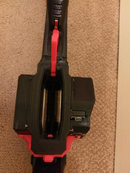
Go ahead and start adding components to the Magwell. Cut the NC terminal off of the switch before screwing it in.
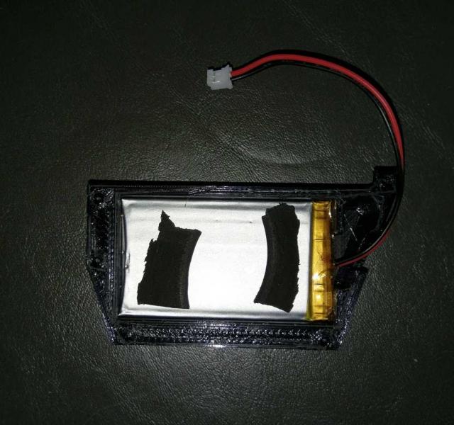
Next glue some foam/rubber to the base of the Lipo Cover. Then insert the battery and put foam on top as well (no glue, this will be a friction fit). We want to sandwich the battery in something shock absorbing. Cut up darts can also work here. Make sure you test fit everything and that the battery is snug, but NOT tight.

Go ahead and plug the lipo into the backpack. Note that your Magwell won’t need those ugly Dremel marks cut in, I have fixed that on the supplied files. Luckily they are hidden by the wire cover anyways.
Now we will begin wiring stuff up.
First get a jumper that is female on one end. Plug the female end into A5 and route to the switch as shown. Measure, snip, strip, and solder. Placing the Ecover on the Magwell will help with routing correctly.
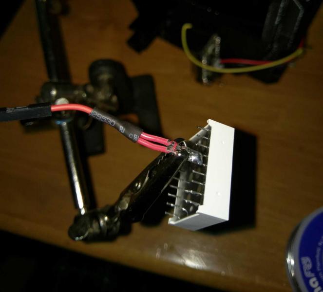
Next cut down the pins on your Ligitek display as shown. Green arrow points to cut pins, red arrow to uncut.
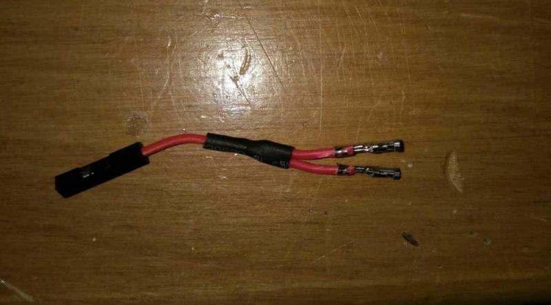
Make wiring for the display anodes as shown. Females on all ends, but the end with two need the black housing removed. This can be accomplished with a knife. Solder to pins 13 and 14 on the display and apply heatshrink. These pins can be soldered together, as I have done. Connect the other end to the 3V pin on the Arduino to make sure everything fits.
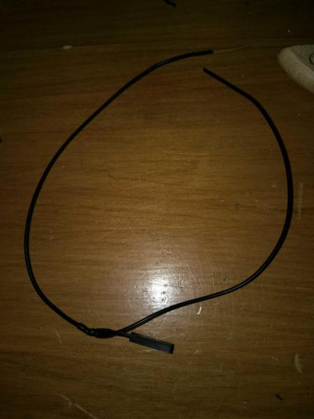
Now make a double ended ground wire as shown. The single end should be female, and the other ends should be bare wire. Note how I criss-crossed the direction of the wires, which is helpful for routing them. Pull one end through hole in the Magwell and out the back. The other needs to be routed and soldered to the other terminal of the mag switch, as shown.
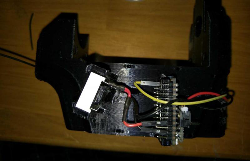
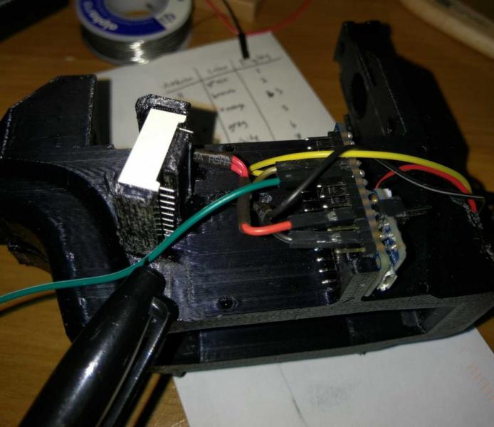
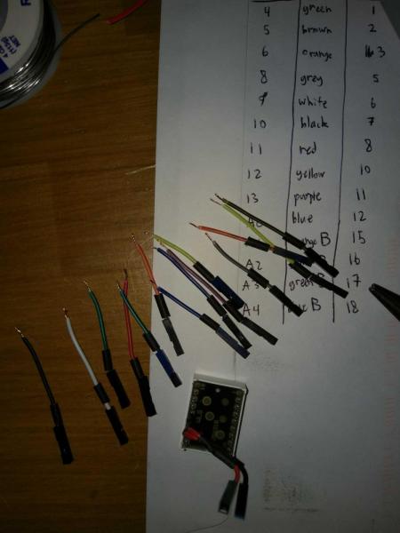
Next figure out the wiring for the LED display. The included pictures follows the pin definitions in the code. These can be interchanged but I recommend following the way I did it, it matches sequential pins. Get different colors for each pin. I ran out of colors, and the “B” added at the end of the last 4 denote that I painted the female ends of the jumpers blue on those wires to differentiate them.

Now we need to cut the wires to size. Test the length needed for each one, and then give yourself an extra 5-10 mm. I tested the length one by one while plugging the female ends into the Arduino and marking where it needed to terminate on the display. After marking everything up cut them to size. And remove the display from the Magwell.
Solder all the wires to the display. This takes some patience. The solder sucker is your friend. I accidentally shorted neighboring pins multiple time and had to resolder. The display is forgiving and the linked item comes with 3 in case you cause thermal damage.

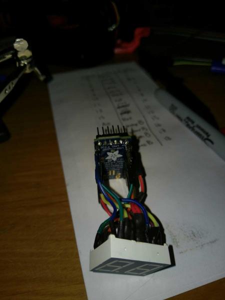
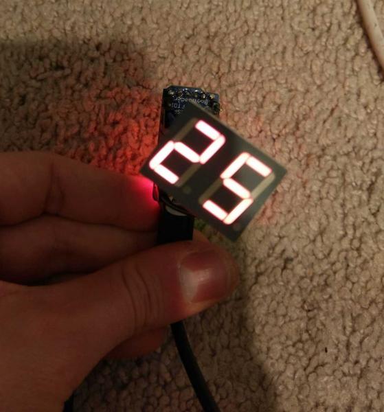
Remove the Arduino from the magwell and wire everything up to test the display. Upload the code and verify that numbers are being displayed correctly. You can short pin 3 to ground to change the numbers to check all of the “pixels”.
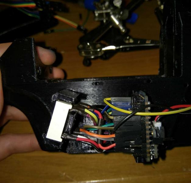
Now unplug everything and begin rewiring with the components installed on the Magwell. Start with the pins on the bottom row. Also, important note, snip the end off of a female jumper. Run the bare wire end through the hole (along with the ground wire from earlier) so it sticks out the back end of the Magwell. Forgot to get an image of this. Plug the female end into pin 3 of the Arduino. This may get removed and re-plugged in as you wire the display to the Arduino, I had to do so several times.
When you get to the last wire on the bottom row, you need to cut one side of the plastic housing off of the female end. This is to make room for the fillet on the Magwell. That fillet is important for strength and is well worth this extra step.
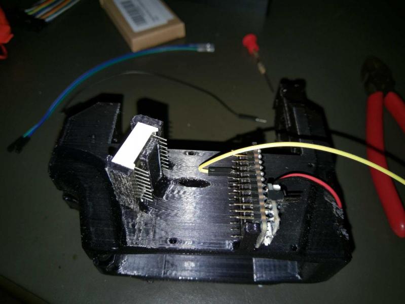
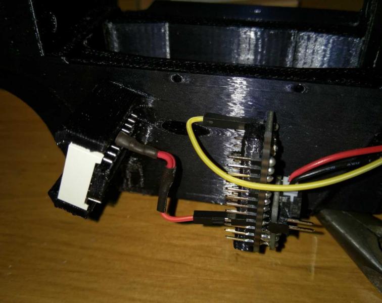
Now wire the top row and replug in anything that you disconnected earlier to give yourself room.
Now we need to bend the pins on the backpack up as shown to make room for the Ecover to slide on. Bend up as shown by the red line.

Go ahead and wire up a slider switch as shown and bolt it to the Ecover. Test to make sure it works (lights come on on Arduino). Affix the switch with 2 M2’s.
Next bolt on the Ecover, and then the Wire cover with M2’s. Congrats, the worst is behind you!
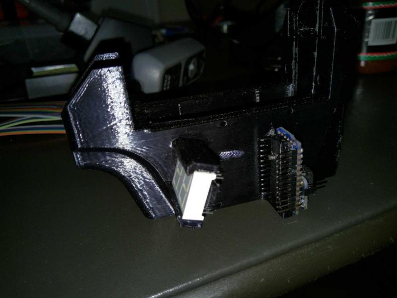
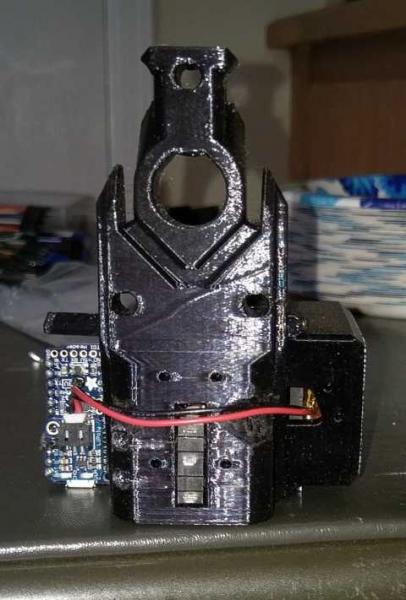
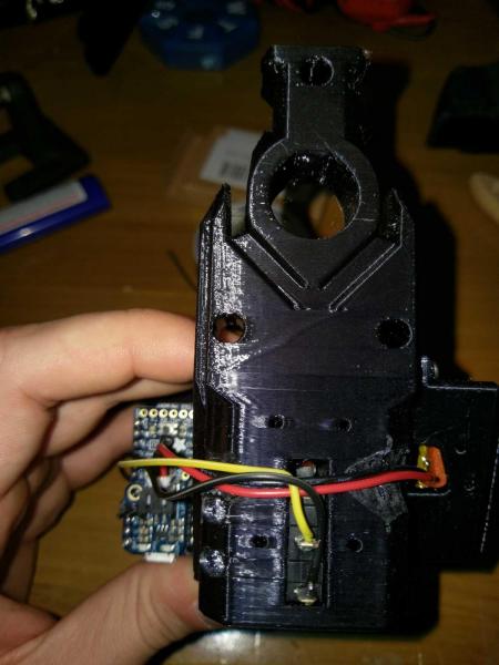
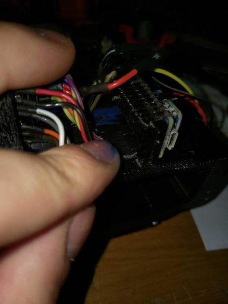
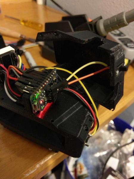
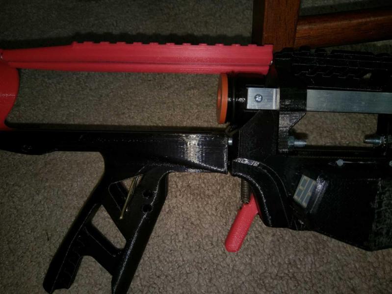
Now we are going to assemble the Caliburn a bit out of order from Slug’s instruction. First assemble all components from muzzle to bore, as in the beginning of his instruction. However before adding anything to the Pistol Grip (like Sear or Trigger) we need to get the trigger switch wired up. Get to the point in the image below. Note that everything forward of the Magwell is tightened down, while everything behind is floating on the threaded rods.
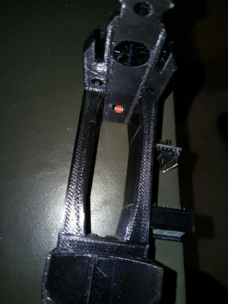
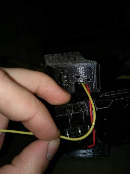
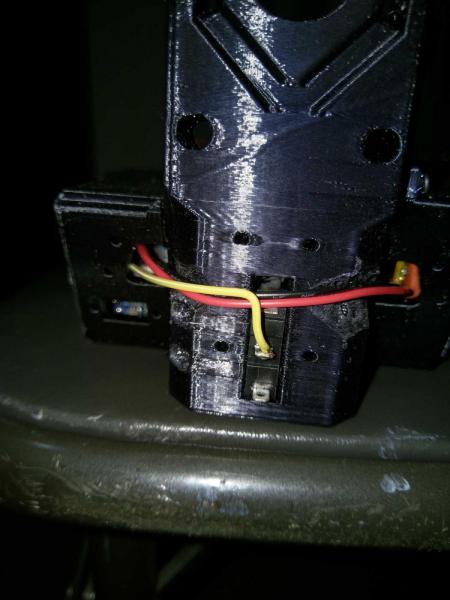
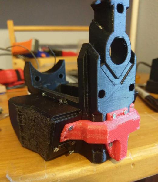
Feed the exposed wires through the hole in the Pistol Grip. My jumpers weren’t long enough and I had to solder on extensions at this step.
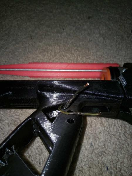
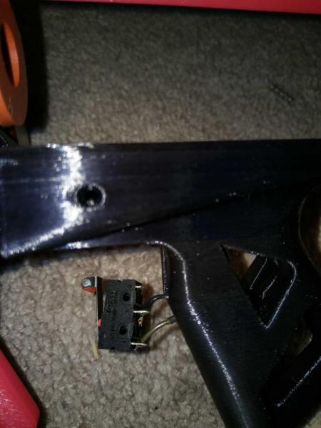
Solder on your wires. As before, snip off the NC terminal. Doesn’t matter which wire goes to which of the remaining two terminals. Carefully insert the switch and bolt down with two M2’s.

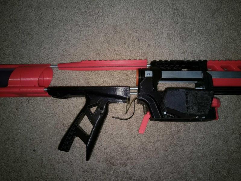
Now assemble the rest of your Caliburn. That’s it! You did it.


Now a quick aside on changing the default mag size values. Open CaliburnAmmoCounter.ino and locate the following line.
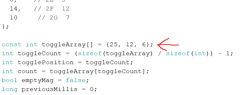
You can change the values in that array to whatever you want and/or add more. You can have only one value as well if you only use one mag type. Just be sure to separate values with commas.
As always, questions, comments, and criticism are all welcome. I hope this guide is a little more straight forward and digestible than my last electronics-y write-up!